Insights
KR Decarbonization Magazine
VOL.04 | Autumn 2023
IMO DCS-based CII rating analysis and CII improvement measures

KIM Donggi, Deputy Senior Surveyor of KR Green Ship Technology Team |
Digitalized regulatory responses,
|
From 2023, it is mandatory for all ships 5,000GT or above to collect emissions data for reporting their annual operational CII and CII rating. As a result, shipping companies are currently focused on the anticipated CII rating results for their ships.
KR conducted preliminary CII rating analysis based on DCS data in 2022, in order to provide advanced CII rating information to shipping companies. This analysis was conducted using 2022 data to consider the ongoing monitoring of 2023 IMO DCS data.

CII rating analysis based on 2022 IMO DCS data
In 2023, about 2,000 IMO DCS data for 2022 were submitted and verified through KR GEARs, and A preliminary CII rating analysis was conducted. The preliminary CII rating analysis results can be viewed in the graphs below.
2022 CII grade preliminary analysis results
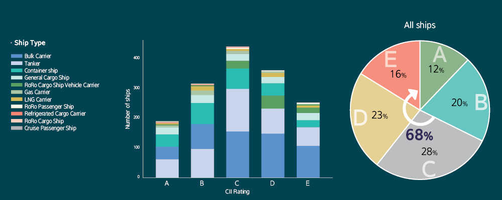
The current distribution of CII ratio was analyzed based on both the number of ships and their ratios. Upon analyzing the CII ratio for all ships, we found that 16% received an E grade, 23% received a D grade, and approximately 28% received a C grade. Through this analysis, it was confirmed that the proportion of ships graded from C to E totaled 68%. Given that C-graded ships are likely to be downgraded to D or E in the future due to yearly tightening of standards, it's clear that not just D and E-graded ships, but also C-graded ships should review and take appropriate measures to improve their CII ratio.
The circle graphs show the CII ratio of four of the ship types (bulk carriers, tankers, container ships, and LNG carriers) submitted to KR.
CII rating ratio by ship type
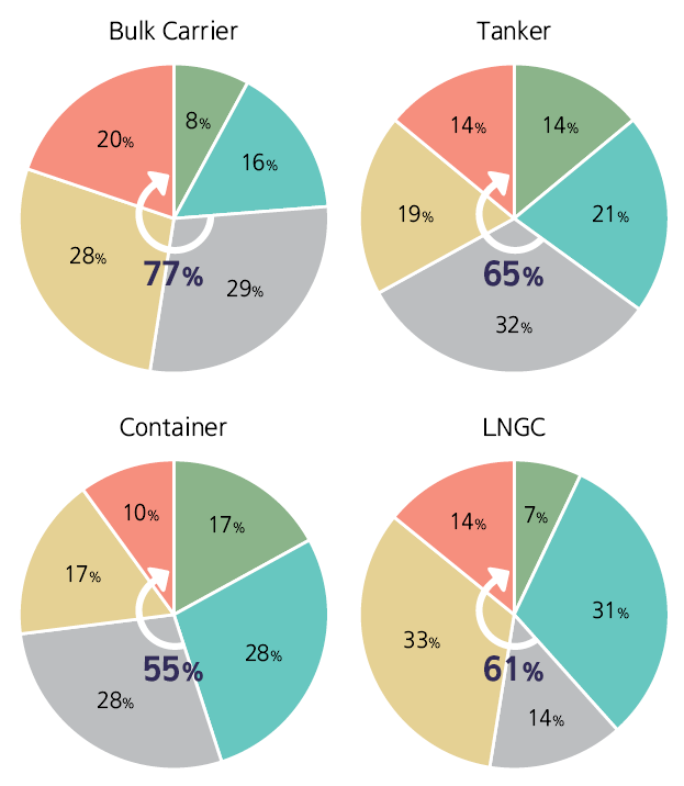
In the case of bulk carriers, the analysis showed that the ratio of C-E graded ships made up 77% of the overall CII rating ratio, which is higher than the overall average of 69%. On the other hand, container ships had a relatively lower percentage at 55%.
Unlike container ships, which mainly consist of liners and have shorter waiting times, bulk carriers and tankers—which have a higher proportion of trampers—tend to have longer waiting times, leading to a higher percentage of C to E CII grades. In the case of LNG carriers, many ships use steam turbines with low thermal efficiency as their propulsion system. As a result, it was found that 61% of these ships fall within the C to E grade range.
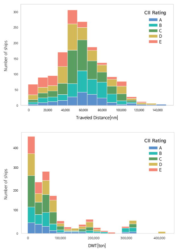
In addition, as a result of analyzing the CII based on the distance travelled and Deadweight Tonnage (DWT), ships with travelling short distances generally have a higher C-E grade ratio, and ships with small DWT compared to ships with large DWT have a higher C-E grade ratio. Furthermore, it has been observed that ships with relatively small DWT and a high proportion of short-distance voyages tend to have a higher proportion of E-grade. Ships with larger DWT and a higher proportion of long-distance voyages tend to have a higher proportion of D to E ratings.
CII rating analysis by traveled distance and DWT
The IMO also recognizes that there are disadvantages in terms of CII depending on ship type, distance travelled, and port waiting time, and will review CII correction factors and voyage adjustments (short distance and port waiting time, Ship-to-Ship for self-unloading bulk carriers, steam turbine propulsion LNGC, fuel consumption of boiler and inert gas generator for gas carriers).
Data anylysis results for an individual vessel
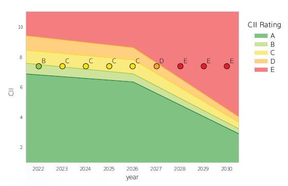
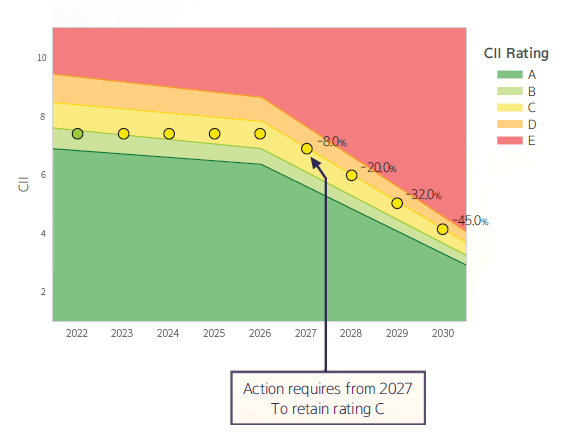
Having examined the analysis results for all ships and individual types of ships in the previous section, let's now turn our attention to the data analysis results for specific vessels. As an example, we analyzed the data of one handy-size bulk carrier, which received a CII rating of B in 2022. Taking into account the 40% reduction target in carbon intensity set by MEPC 80 compared to 2008 levels, we are assuming an annual reduction rate of 2.75% from 2027 to 2030. We have analyzed the projected CII grades from 2023 onwards for this vessel. The analysis is represented in the graph on the right. The graph illustrates the grade progression up to 2030 without implementing CII improvement measures. The graph on the right shows the required greenhouse gas reduction as a percentage to maintain at least a C-grade rating.
The CII rating of the example ship is expected to change to C grade from 2023 to 2026, D grade in 2027, and D to E grade from 2028. Improvement measures should be taken to maintain at least C grade from 2027.
CII rating change without improvement measures
GHG reductions(%) required to maintain a C rating
Measures to improve the CII rating of existing ships
What measures can the shipping company take to improve the ship's CII rating?
One of the first measures to implement in order to improve the CII rating is to reduce ship speed. However, when it comes to ship operation, the ship speed is reduced to the lowest feasible level. If further greenhouse gas reduction is needed, additional measures such as ship speed and route optimization through weather routing, on-time arrival, optimal trim maintenance, and periodic propeller and hull cleaning should be implemented in parallel.
Secondly, fuel conversion can be considered. The first feasible alternative at this point is to use biofuels. The IMO's MEPC 80 meeting recently approved MEPC.1/Circ.905 of the Interim Guidelines on the Use of Biofuels in terms of Rules 26, 27 and 28 (DCS and CII) of MARPOL Annex VI. It is expected that greenhouse gas reduction effects can be obtained by using biofuels that satisfy the requirements presented in these guidelines. However, given the instability in fuel supply, it's important to secure a reliable source to ensure sufficient fuel availability. Additionally, the higher cost compared to existing fuels must be taken into account.
Third, energy efficiency is improved by applying technology that can reduce ship resistance or improve propulsion efficiency. The easiest way is to apply low friction paint, replace the propeller with one that fits the lowered speed, and install an energy efficiency improvement device (ESD).
However, a cautious approach is needed, taking into account the uncertainty surrounding the greenhouse gas reduction impact of energy efficiency improvement devices, as well as CAPEX and OPEX considerations.
The measures introduced above are the most typical measures, and it is desirable to select an appropriate combination for each ship after reviewing all applicable measures, rather than applying only one of the measures mentioned above. For example, after applying route optimization technology through ship speed reduction and weather routing, a certain amount of biofuel can be used. Even in the case of biofuels, biofuels with different blending ratios can be supplied and used according to the required amount of greenhouse gas reduction.
Digitalization of regulatory response to effective decarbonization response
At the moment, if a ship doesn't meet the target C-rating required by the CII regulations, the only penalty is to submit SEEMP Part III with a plan of corrective action and get it approved again. There are no clear guidelines such as detention. This has resulted in some shipping companies not taking proactive measures. However, by January 1, 2026, there may be discussions about implementing stricter penalties, such as detention, for ships that haven't taken corrective actions. Therefore, it's crucial for companies to proactively work on reducing greenhouse gas emissions well in advance.
To support the shipping company's response to greenhouse gas regulations, KR is providing a one-stop total solution that can respond to CII, EU/UK MRV and ETS regulations through KR GEARs. Shipping companies can respond to CII regulations through CII monitor functions that can derive and manage CII ratings based on real-time operational data and CII simulator functions through the establishment of ship-specific improvement scenarios.
In addition to this, KR plans to annually provide a GHG Counter Measure Advisory Report based on verified DCS data. This report will include information on CII status, comparisons with other ships, and the necessary reduction quantities of greenhouse gas emissions to achieve expected CII grades by 2030 and higher. Each shipping company will receive a copy of the report, which is expected to serve as a valuable resource for future planning and decision-making related to CII regulations.
In conclusion, KR believes that, in response to the accelerating decarbonization efforts in the maritime sector, digitalization is essential for regulatory compliance. Regulatory digitalization enables effective proactive responses through quality data collection, management, and real-time operational monitoring. This, in turn, facilitates the formulation of strategies for CII regulation compliance and decarbonization efforts. KR is committed to continually updating KR GEARs functionality and providing the support for digitalization initiatives and maritime decarbonization.
The Evolution of Alternative Ship Fuels and Fuel Containment Systems

SHIM Youngjin, Senior Surveyor of KR Business Support Team |
Various aspects of fuel storage systems
|
Outlook and selection of alternative ship fuels
Until recently, only one type of fuel based on fossil fuels was predominantly used for ships. However, from the mid-2000s onwards, we are now transitioning to an era where a diverse range of fuels are employed, according to the unique advantages and disadvantages of each fuel, variations in technology and commercial maturity, and the distinct requirements of different ship types. Discussions about future alternative fuels include LNG, LPG, methanol, ammonia, ethanol, hydrogen, batteries, and small nuclear reactors, among others. Over the past decade, the share of LNG as an alternative fuel has increased, and methanol is also gradually gaining traction. However, methanol fuel is predominantly being considered for specific vessel types like container ships. On the other hand, ammonia, hydrogen, and small nuclear reactor fuels are not yet used as ship fuels due to technical and toxicity-related challenges.
For these fuels to be used in ships, essential steps like engine development are necessary. In the case of ammonia, it is anticipated that after the development of main engines around 2024-2026, orders for ammonia-powered vessels will increase. Following that, Fuel Selection is expected to change with hydrogen, small nuclear reactor technology, and others.
Choosing a fuel is a complex decision that involves considering various factors like fuel prices, equipment costs, decarbonization regulation expenses, retrofitting costs, etc. Amidst such uncertainties of the future, shipping companies need to devise strategies that align with their situations. Due to various possibilities, concepts like fuel diversity, fuel mosaic, and fuel flexibility are becoming increasingly important. In this context, both alternative fuel engine technology and fuel storage system technology significantly impact aspects like vessel deployment, construction costs, and maritime operations. Therefore, let's explore fuel storage technology from the perspective of decarbonization in the maritime industry.
World Fleet Fuel Selection Status
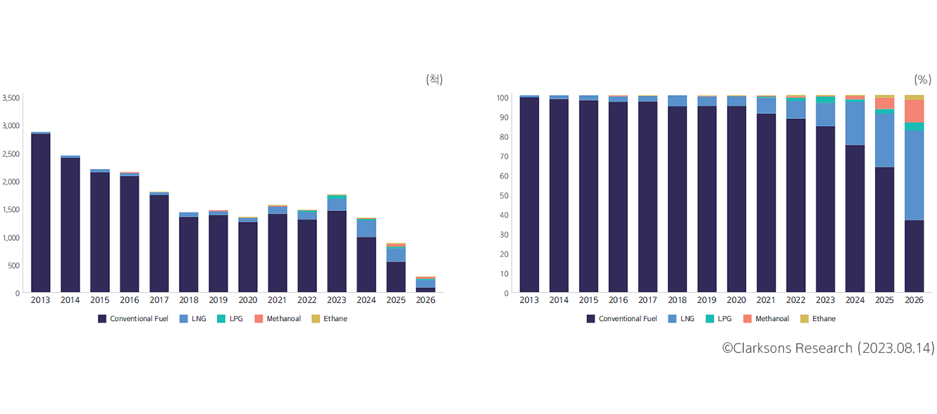
Order Book by Ship Type and Fuel Status
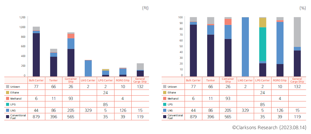
Types and materials of future alternative fuel containment systems
· Choosing alternative fuel containment systems
The various options for alternative fuels make ship design more complex. Even for similar types of ships, the choice of alternative fuel affects the type, placement, and materials of fuel tanks. These differences have an impact on the whole ship.
The following flow chart suggests a successful design process Various aspects of fuel storage systems for an alternative fuel storage system.
Alternative Fuel Storage Tank Design Flow Chart
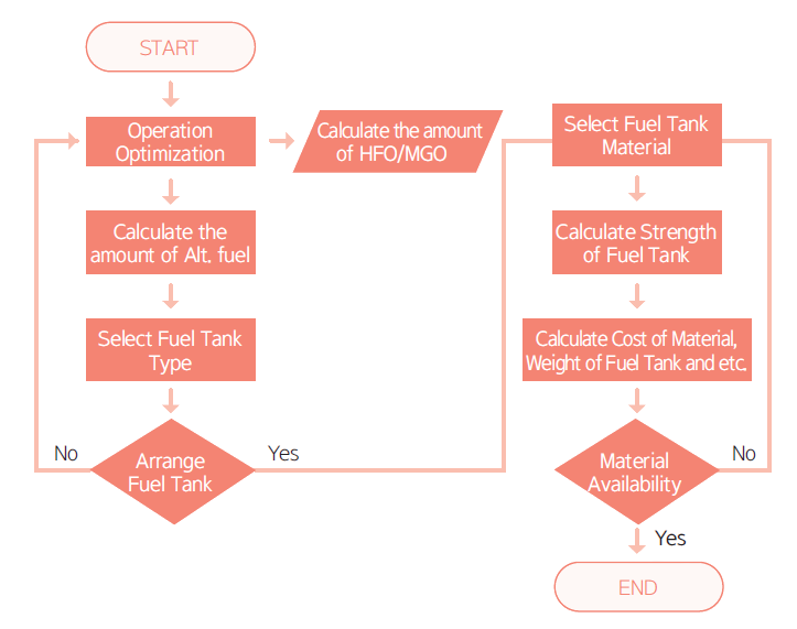
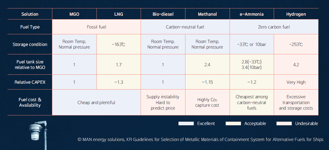
The first important step is to optimize the ship's operations. The amount of fuel needed depends on the route and distance the ship travels. Once we calculate the quantity of conventional fuels like Heavy Fuel Oil (HFO) or Marine Gas Oil (MGO) required for the journey, we can then determine the amount needed if we switch to an alternative fuel. Different alternative fuels have varying energy densities, so the amount of fuel needed for the same distance varies. For instance, if we want to use e-methanol fuel for the same journey as MGO, we would need a fuel tank for methanol that is 2.4 times larger than the MGO tank.
Fuel Comparison Table
· Types of alternative fuel containment system
Once we have determined the quantity of alternative fuel we require, we must decide on the type and location of the fuel tank. Ship fuel storage tanks generally fall into three categories: those using regular ship hull space, independent type A, B, and C tanks according to IMO standards, and membrane-type tanks. When a relatively small amount of fuel is needed, independent type C tanks are used, and for larger fuel quantities, independent type A, B, or membrane-type tanks are employed. However, for methanol fuel tanks, a common type similar to traditional HFO fuel tanks is possible, allowing for more flexibility in tank size and design compared to other fuel tanks.
Illustrates the typical tank types that can be used for alternative fuels.
Classification of Alternative Fuel Tank Type
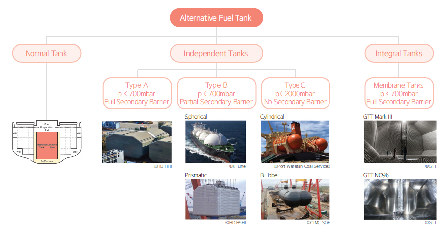
Independent Type A tanks are designed according to criteria recognized by the traditional ship strength analysis methods used by KR. They should have a design vapor pressure of less than 0.07 MPa and can be designed similarly to the ship's structure, which offers space efficiency compared to indepedent Type C tanks. To ensure against liquid fuel leakage, a full secondary barrier is also required. Independent Type B tanks are precision-designed using detailed analysis methods to determine stress levels and fatigue life. They should have a design vapor pressure of less than 0.07 MPa, and provisions for safe handling and removal in case of partial secondary barrier rupture or leakage are necessary. Independent Type C tanks are based on pressure vessel standards, and they are designed to ensure that surface defects do not progress more than half the thickness of the tank's outer shell over the tank's lifespan. As a result, secondary barrier installation is not required. Membrane tanks have thin walls made of a membrane that prevents liquid leakage, and the load of the fuel is supported by the adjacent internal hull through insulating material on the outer side of the tank.
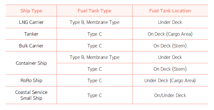
Once the type of the fuel tank is determined, the placement of the tank needs to be chosen. For independent Type A, B, or membrane tanks, due to factors like tank size and secondary barriers, it is difficult to place them outside of below the cargo area main deck, regardless of ship type. On the other hand, independent Type C tanks can be positioned both above and below the main deck, but they tend to occupy relatively more space. Common locations for independent Type C tanks include the upper deck of the foredeck for bulk carriers, the upper deck of the cargo area for tankers, and the lower deck of the cargo area for roll-on/roll-off (ro-ro) ships.
Common Alternative Fuel Tank Type and Location
If a fuel tank of the required capacity cannot be accommodated on the vessel, there may be instances where the fuel tank size needs to be reduced or the shape of the existing hull altered. These challenges in fuel tank placement are among the factors that complicate the transition to alternative fuels for currently operating vessels that did not account for alternative fuel tanks in their initial design.
· Materials of alternative containment systems
The materials for fuel storage tanks are determined by the characteristics of each alternative fuel, the design temperature, and the design vapor pressure. For LNG fuel, a design temperature of -163 degrees Celsius and a design vapor pressure of less than 0.7 bar are required. Consequently, materials like austenitic stainless steel, nickel alloy steel, aluminum alloy steel, and high-manganese steel are used for LNG fuel tanks to maintain strength, toughness even in extremely low temperatures, and sufficient impact resistance. On the other hand, for methanol, which boils at 64.7 degrees Celsius at atmospheric pressure, the use of low-temperature resistant steel is unnecessary. However, since methanol can corrode certain materials, additional measures for fuel tank coating are necessary. Ammonia fuel tanks typically require the use of low-temperature resistant steel capable of enduring -55 degrees Celsius. Liquid hydrogen fuel tanks, on the other hand, require materials that are not sensitive to hydrogen.
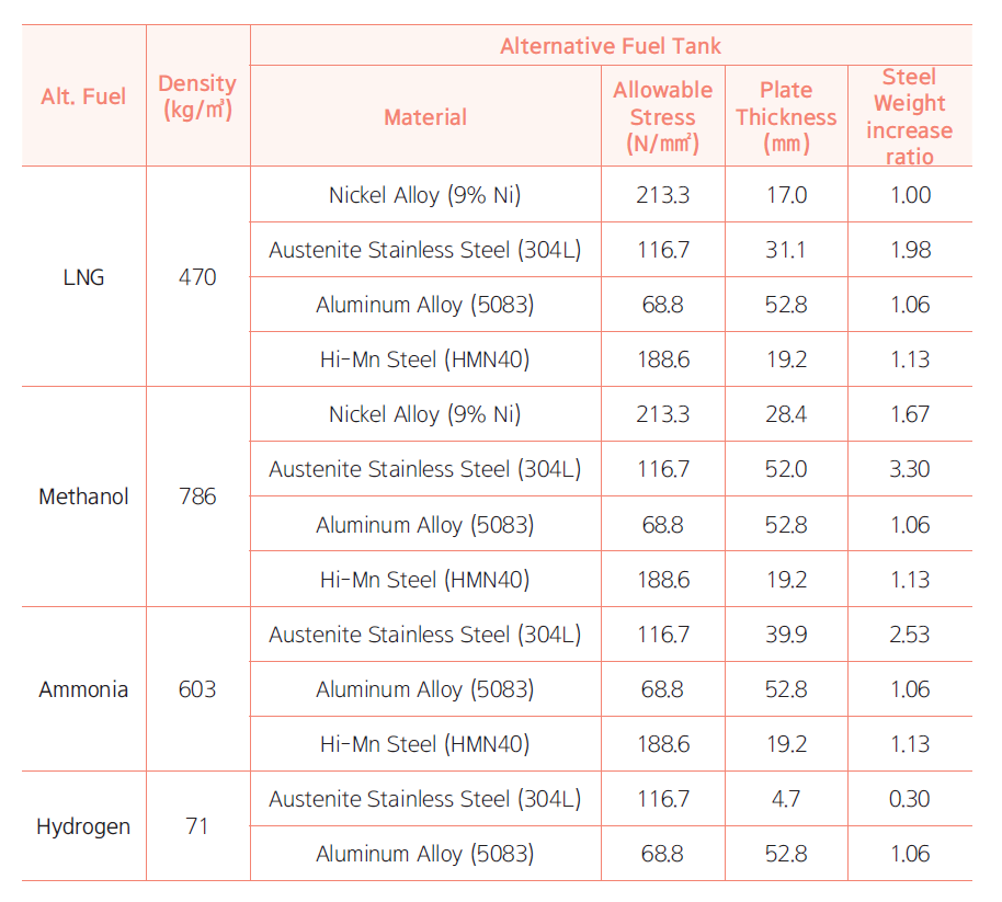
When choosing materials for fuel tanks, the cost of materials will likely have the most significant impact. However, in the design process, the weight of the fuel tank is as important as the cost of materials. Due to varying densities of alternative fuels and differences in material properties, the required thickness for a fuel tank to meet structural strength can vary. This can result in variations in the weight of the fuel tank supporting structures, potentially necessitating additional reinforcement.
The following table illustrates the relationship between the density of alternative fuels, required material thickness, and the resulting increase in the weight of the fuel tank, using the example of an LNG fuel tank made from 9% nickel alloy steel.
Fuel Tank Weight increase ratio of Type C tank
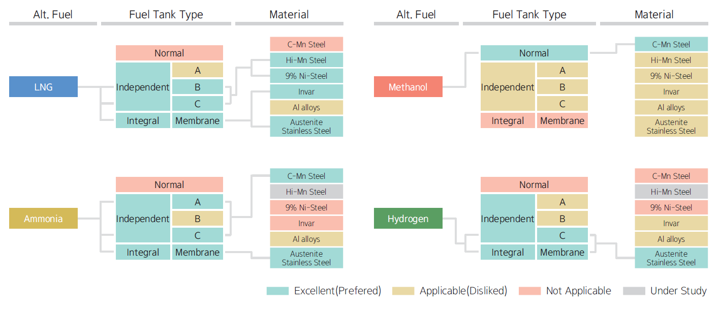
Considering all these factors, for standalone Type A, B, and C tanks for LNG fuel, the main materials will likely be 9% nickel alloy steel or high-manganese steel, and for membrane-type tanks, austenitic stainless steel or INVAR are used as primary barrier material. For methanol and ammonia fuels, carbon-manganese steel is expected to be the primary material, while for hydrogen fuel, austenitic stainless steel is likely to be the main choice.
When it comes to aluminum materials, the weight of the fuel tank is not significantly different from that of a 9% nickel alloy steel. However, the need for a tank with more than three times the thickness increases welding costs and the risk of welding defects, which reduces the preference for this material.
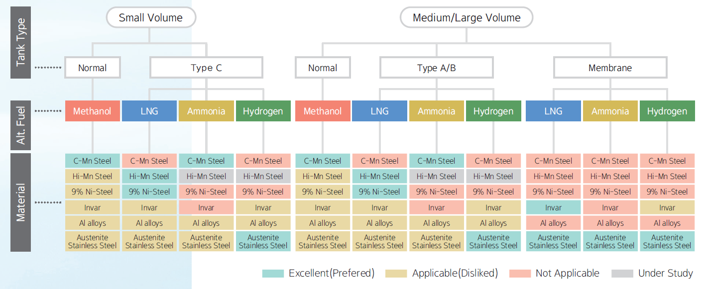
The diagram below illustrates the sequence from required fuel capacity, fuel tank type, to fuel tank material selection as described so far.
Classification of Fuel Tank Material (1)
The following diagram illustrates the preferred fuel tank types and materials for each alternative fuel, presented in a different order. Considering the materials for fuel tanks during the design phase is an important factor in preparing for fuel conversion.
Classification of Fuel Tank Material (2)
Impact of fuel storage selection on future alternative fuel transition
· Methanol fuel retrofit conversion for container ships
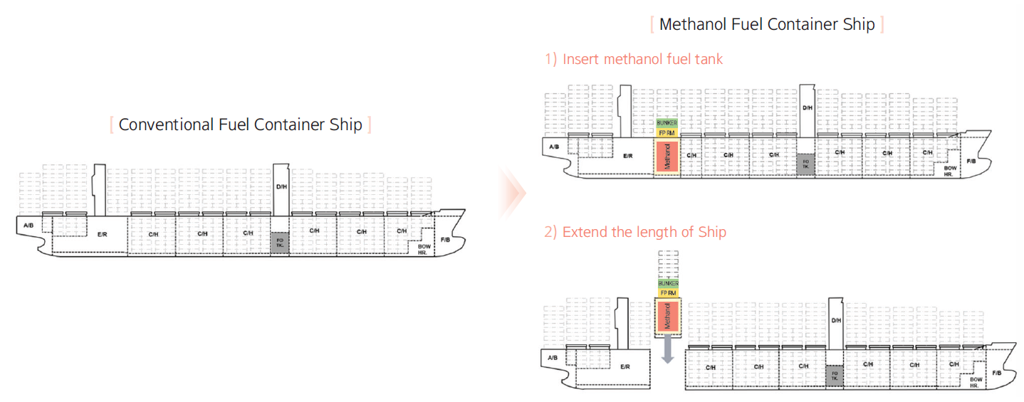
As interest in methanol increases, there is a growing trend to retrofit existing fuel-powered container ships to run on methanol. However, transitioning to a fuel not initially considered and planning for its future use in a retrofit is quite challenging and requires significant investment. There are two methods of conversion of container ships to methanol propulsion: inserting methanol fuel tanks into existing cargo hold spaces to replace cargo space with fuel tank capacity or extending the ship's length by the required length of the methanol fuel tanks. The method of inserting fuel tanks is expected to result in cargo loss and constraints in tank design. On the other hand, extending the ship's length to accommodate fuel tanks will avoid cargo loss, but it introduces many additional considerations due to the extended hull length. Both options present complex challenges.
Example of Methanol Fuel Retrofit
· Utilization of existing HFO tanks as methanol fuel tanks
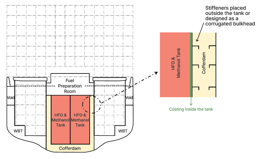
Can we repurpose existing HFO tanks for methanol fuel? This is generally considered difficult. The challenge arises from the properties of methanol, which can corrode certain materials, making tank coating crucial. Moreover, due to its toxicity, a cofferdam* must be placed around the methanol fuel tank. HFO tanks designed without accounting for these methanol-specific properties would likely lack tank coating and cofferdam structures. Specifically, the reinforcing materials inside HFO tanks hinder the quality of tank coating. Therefore, if designing tanks for a vessel prepared for both HFO and methanol storage, the cofferdam structure should be considered from the outset. Reinforcement materials should either be placed outside the tank for coating purposes, or a corrugated bulkhead should be used to form the fuel tank.
* Cofferdam : an empty space arranged so that compartments on each side have no common boundary
Example of HFO & Methanol Fuel Tank design
· Impact of fuel storage on retrofit costs
As mentioned earlier, retrofitting for a different fuel propulsion involves significant costs and time. Research reports on fuel conversion retrofits show that costs can vary by vessel type, ranging from as low as 50% to over 100% of the vessel's value, and the conversion process can lead to 4 to 6 months of lost earnings due to downtime. These factors make it challenging to retrofit operational ships for alternative fuel propulsion. This is one of the reasons why there is an increasing focus on building new ships designed for alternative fuels, which can help reduce the costs associated with future retrofits.
Conclusion: Importance of fuel storage technology
We have examined various aspects of fuel storage systems and their impact on transitioning to alternative fuels to meet decarbonization needs in the shipping industry. The role of fuel storage systems in a successful transition to alternative fuels is both significant and vital. Since the introduction of LNG-powered ships, vessels prepared for alternative fuels have been considered. However, the tangible benefits of these preparations have been met with skepticism to date. The uncertain future makes immediate decision-making and investment during the design phase challenging. Nevertheless, the push for decarbonization in shipping is growing, affecting not just new builds but also existing vessels, and coming from multiple angles. Fuel storage systems demand significant collaboration and practical solutions from shipping companies, shipbuilders, energy providers, and others. This article aims to serve as a starting point for these discussions, and we hope that KR can contribute to these collaborative efforts.
CCUS Industry and LCO₂ Carrier

LEE Dongbeom, Senior Surveyor of KR Liquid Cargo Ship Team |
To ensure
|
CCUS technology and carbon neutrality efforts
The rising emissions of greenhouse gases pose global challenges related to climate change and global warming. Both countries and companies are striving for carbon neutrality to fight these issues. Carbon Capture, Utilization, and Storage (CCUS) technology has gained traction as one solution in the fight against greenhouse gas emissions.

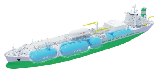
CCUS industry and LCO₂ carriers
Its high demand has spurred the expansion of the CCUS industry and galvanized the need for specialized liquefied carbon dioxide (LCO₂) carriers. Stable and large-scale transport of captured carbon dioxide (CO₂) by CCUS processes to storage facilities requires specific conditions, such as low temperatures and high pressure. LCO₂ carriers are designed to handle these particular tasks.
While CO₂ exists in a gaseous state at room temperature, it is crucial to transport CO₂ in a liquid state. IMO Type C tanks should be employed for the efficient bulk transportation of liquefied CO₂. LCO₂ carriers must be designed carefully considering the triple point conditions, where gas, liquid, and solid states coexist. Special attention is crucial to prevent any phase transition during the operation. Furthermore, while the International Code for the Construction and Equipment of Ships Carrying Liquefied Gases in Bulk (IGC Code) classifies CO₂ only as an asphyxiate cargo, many countries classify CO₂ as a toxic substance. As a result, the International Maritime Organization (IMO) has initiated discussions on this matter. If CO₂ were to be classified as a toxic substance, it would be subject to additional safety requirements in the IGC Code related to the transport, storage, and handling of toxic substances. However, the toxicity of CO₂ is not as severe as other toxic substances, so it is expected that some regulations may be exempted. As such, it's important to monitor the future discussions and decisions of the IMO.
Hanwha Ocean 40K LCO₂ Carrier
Various factors to consider in designing tanks for the safe transportation of LCO₂
· Tank pressure
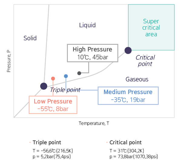
The design pressure of the tank can be classified into low pressure and medium pressure. The choice depends on several factors, including the amount of cargo transported, the distance to the final storage facility, impurity levels, and the state of the captured CO₂. From an operational flexibility perspective, medium pressure offers advantages over low pressure. However, increasing pressure during tank design results in thicker tank shells. It poses a challenge for medium pressure tanks as there are limitations in steel thickness for cargo tanks, making it challenging to achieve larger tank sizes. Conversely, low pressure tanks allow larger sizes. However, there is a higher risk of dry ice formation due to operating temperatures and pressures being close to the triple point compared to situations with medium pressure.
Triple Point of Carbon Dioxide
· Low temperature
CO₂ is transported at low temperatures, around -55 degrees Celsius for low pressure and -35 degrees Celsius for medium pressure tanks. Consequently, the selection of tank materials that meet the low temperature requirements specified in the IGC Code is of utmost importance.
· High density
In a liquid state, CO₂ exhibits a density of around 1.15 ton/m³, which makes it approximately twice as dense as LPG. The challenge necessitates further scrutiny regarding fatigue, as per UI GC7, and consideration of sloshing due to the higher density.
· Purity
The vapor pressure of CO₂ varies significantly based on its purity. Typically, LCO₂ carriers are designed with a consideration of high purity CO₂. When accounting for vapor pressure fluctuations due to purity, it is crucial to consider higher vapor pressures. Additionally, the moisture content of CO₂ can also impact tank corrosion and requires careful attention.
· Tank plate thickness
The IGC Code permits steel plate thicknesses up to 40mm for independent Type C tanks. Steel plates with thicknesses ranging from over 40mm to under 50mm necessitate either Post Weld Heat Treatment (PWHT) or Engineering Critical Assessment (ECA) under IACS UR W1. For larger tanks, considering the challenges of Post Weld Heat Treatment (PWHT), there is a greater likelihood of employing Engineering Critical Assessment (ECA). To facilitate this, IACS intends to establish a project team to develop an ECA procedure.
· Tank shape
Ease of fabrication and design efficiency may determine the shape of the tank as a single cylindrical Type C tank. Another option is a multi-lobe Type C tank, which is more challenging to fabricate and design but easier to use.
Ammonia and LCO₂ carrier
Recently, there has been a growing number of articles discussing advancements in ships capable of transporting both ammonia and LCO₂. The plan is to use one ship to carry ammonia to power plants and then use the same vessel to transport emitted CO₂ to storage facilities. This strategic approach offers notable operational efficiencies. However, how the residual ammonia left after ammonia transport affects CO₂ purity needs to be considered. Failing to properly clean the tank before loading carbon dioxide after discharging ammonia could impact CO₂ purity. Additionally, the vapor pressure dynamics of CO₂ could have significant effects. It is imperative to subject the cargo handling system (CHS) to a comprehensive cleansing procedure. This might necessitate separate cargo handling systems for both ammonia and CO₂. Cross-loading of LCO₂ with ammonia in a single tank poses practical challenges.
Our roles
In close synergy with various shipyards, KR has successfully completed the verification of structural integrity and fitness for the cargo tanks and holds of LCO₂ carriers. Through rigorous analysis in accordance with requirements mandated by the IGC Code, KR has confirmed the structural integrity of cargo tanks under various load conditions, including permanent, functional, environmental, and accidental loads. Beyond this, the structural reliability of cargo holds, and tank support structures has undergone validation across a range of design load conditions. KR is committed to being a steadfast partner for pioneering entities navigating decarbonization, a mission fostered by such close collaborations.